Setting
As can be seen from the minimal connection diagram, for the controller to operate, 3 input signals are sufficient:
throttle position;
engine speed;
pressing the brake.
Attention
An important output signal from the controller is “Clutch out.”. It is necessary to connect this output to the ECU and implement automatic torque limitation on shifts. The controller and gearbox can operate without this signal, but this will lead to a stretching of the shift time and faster wear of the clutch pack.
Thus, the basic algorithm for setting up the controller is as follows:
Enter in the configuration parameters:
TPS min. [V]TPS max. [V]TPS idle speed [%]TPS kickdown [%]Torque max. [Nm]Target idle speed [rpm]Select in settings the algorithm calculation of torque by TPS.
As a first approximation, set the desired values in the torque table.
Configure the engine ECU torque limitation on gear shifts.
Set torque on wheels.
Torque calculation
In our version, 4 options for calculating the moment are implemented:
Each option has its own advantages and disadvantages.
TPS
Tabular version of calculating torque based on revolutions and throttle position.
- Advantages:
simplicity;
works in all modes.
- Disadvantages:
there is no direct connection with the engine torque.
Tip
This option is quite sufficient for naturally aspirated and light/medium turbo cars.
To work in this mode, the basic setting algorithm is sufficient.
MAP
Tabular version of torque calculation based on revolutions and absolute pressure sensor.
The most reliable option for work, in our opinion.
- Advantages:
works in all modes.
there is a direct connection with the engine torque.
- Disadvantages:
signal from absolute pressure sensor required.
To work in this mode, in addition to the basic setting algorithm, you also need:
Add signal from absolute pressure sensor (A6) to minimum connection.
Enter in the configuration parameters:
MAP voltage min. [V]MAP voltage max. [V]MAP pressure min. [kPa]MAP pressure max. [kPa]MAP max. pressure in car [kPa]Select in the configuration the algorithm for calculating the torque by the MAP.
Injector
Tabular version of torque calculation based on revolutions and signal from the injector. In this mode, the filling of the PWM signal (Duty) from the injector is estimated.
Tip
Not recommended for use.
- Advantages:
there is a direct connection with the engine torque.
- Disadvantages:
does not work correctly in cutoff mode;
operation is possible only in phased injection mode;
signal from injector required.
To work in this mode, in addition to the basic setting algorithm, you also need:
Add signal from injector (A5) to minimum connection.
Select in the configuration the algorithm for calculatingthe torque by the injector.
Formula
A variant of calculating the torque using a formula. In this mode, the injection time from the injector is estimated and the engine configuration is taken into account.
Tip
Not recommended for use.
- Advantages:
there is a direct connection with the engine torque;
the actual engine torque is calculated.
- Disadvantages:
does not work correctly in cutoff mode;
operation is possible only in phased injection mode;
signal from injector required.
To work in this mode, in addition to the basic setting algorithm, you also need:
Add signal from injector (A5) to minimum connection.
Enter in the configuration parameters:
Number of cylindersInjector flowBSFCSelect in the configuration the algorithm for calculatingthe torque by the injector.
Torque limitation
For the correct operation of the gearbox, it is necessary to limit the engine torque when shifting gears.
As can be seen from the minimal connection diagram, thecontroller has a clutch output (B4).
At the moment of switching, a voltage of +5V appears on this output. It is necessary to connect this output to the engine ECU and set up torque limitation (Shift-Assist).
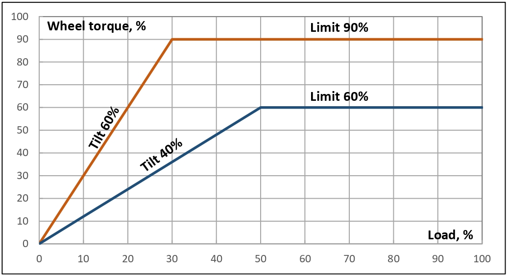
Torque on wheels
The torque on the wheels is a calculated parameter that affects the shift points and the rigidity of the gearbox operation. In our implementation, it is formed from two values in the configuration:
Wheel torque limit [%]Wheel torque increase [%]
The meaning is visually presented in the figure below.
Set the limit to 100%.
Set the increase to 30%.
Add a 10% slope and watch the gearbox reaction.
In case of inappropriate behavior or errors - reduce by 10%limit until normal operation.
Speed output
To minimal connection additionally connect the wire from the engine ECU speed sensor input to the output (B3) of the controller.
Attention
This output only works when the “DSG Diagnostics” flag is enabled in the configuration section. The speed information is extracted from the mechatronics diagnostic package.
Reverse output
To minimal connection additionally connect the wire from the reversing lights to the output (B1) of the controller.
When the selector is switched to reverse gear mode, the output (B1) will show +12V. Maximum current - 5A.
Launch
- To minimal connection additionally connect:
activation button between the car body (ground) and the input (A4) of the controller;
wire between the Launch activation input in the engine ECU and the output (B2) of the controller;
In configuration configure the parameters:
Launch. Clamping stiffnessLaunch. Throttle threshold [%]
Tip
It is recommended to use a clamping stiffness of 0 (without preload).
The algorithm for activating Launch mode is as follows:
Press the brake.
Enable selector mode D, S or TT.
Press the Launch activation button.
Depress the gas pedal fully.
At the right moment of start, release the brake and the Launch activation button.