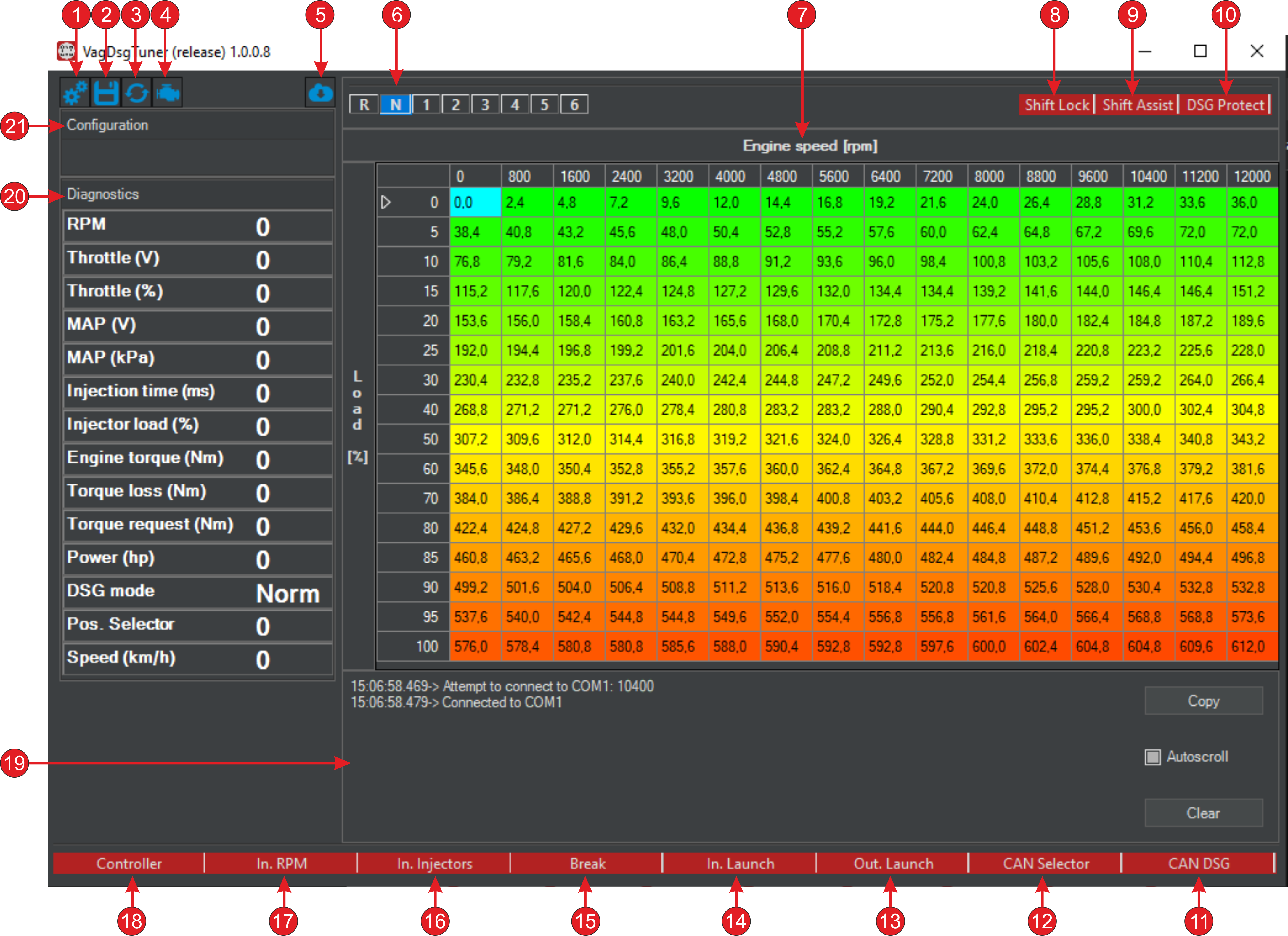
User interface
Number |
Purpose |
|---|---|
1 |
Calling the configuration menu |
2 |
Save the table to the controller’s Flash memory |
3 |
Save the table in the controller’s RAM memory |
4 |
Calling up the DSG mechatronics error menu |
5 |
Calling up the controller firmware update menu |
6 |
Active transmission in DSG |
7 |
Customizable torque table for sending to DSG |
8 |
Selector Lock Solenoid Status |
9 |
Momentum cutting mode status |
10 |
DSG protection mode status |
11 |
State of the communication line with mechatronics |
12 |
State of the communication line with the selector |
13 |
Launch Control activation output status (on ECU) |
14 |
Launch Control Activation Input State (to controller) |
15 |
Brake pedal condition |
16 |
Injector Input State |
17 |
RPM Input Status (from ECU) |
18 |
Communication status with the controller |
19 |
Event log in shell |
20 |
Area with diagnostic parameters |
21 |
Area with the name of the current configuration in the controller |
Important
For all status indicators, red color is inactive state (off), blue color is active state (on).
Torque table
Setting up the table consists of changing the torque values depending on the engine speed and load.
Important
Load is understood as a standardized range of 0 - 100% to which the values of TPS, MAP, and Injector are reduced, depending on the selected algorithm torque calculation.
The change can be made in a single cell or in a selected group of cells.
Moving between cells is done by clicking the mouse or using the buttons on the keyboard:
Up;
Down;
Left;
Right.
Selecting a group of cells is done by moving the mouse cursor while holding down the left button, or by using the keys on the keyboard:
Shift+Up;
Shift+Down;
Shift+Left;
Shift+Right.
Changing values:
L - increase;
K - decrease;
Shift+L - quick increase;
Shift+K - quick decrease
I - interpolation.